Clamp-On Ground Testing Comparison

On April 14, 2002, a ground resistance test was conducted to
compare the results obtained from the Fall-of-Potential 3-Point testing
method to the clamp-on testing method. The grounding system
consisted of four copper clad rods installed in an approximate 20 ft
square. Three of the rods are 5/8" in diameter and 10 ft in length. The
fourth rod is 1/2" in diameter and 8 ft in length. All rods were coupled
together with #3 AWG solid aluminum wire with brass mechanical
connections. Figure 1 shows the schematic of the system.
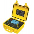
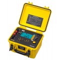
The tests were conducted with the following equipment manufactured by AEMC® Instruments
Additionally, we used the AEMC® Model 6240, a micro-ohmmeter to verify the
bonding of the aluminum wire to the individual ground rods.
The soil conditions in the test area were predominately loam with some gravel.
Conditions on the day of the test were dry and sunny, some light rain had
occurred the day previous to the test. Therefore, the soil was somewhat moist at
the surface.
The AEMC® Model 6240 Micro-Ohmmeter was used to measure bonding
resistance at each rod and was the first test completed. Measurements from
each conductor to the rod were taken as well as measurements from conductor
to conductor through the rod and clamp. Readings on rod number three ranged
from 615 to 733µΩ at each bonding point, indicating that all connections were
good. See Figure 2 for full results.
| Measurement Point | Resistance (µOhms) |
| A to B | 713 |
| C to B | 615 |
| A to C | 733 |

The AEMC® Model 6470-B was used as 3-Point ground tester. Rod number three was first disconnected from the other rods in the system so that its individual resistance could be measured. The X lead was attached to rod number three (see Figure 3). The Z lead was attached to an auxiliary electrode 100 feet away and the Y lead was initially connected to the auxiliary electrode 60 feet away. Readings were taken with the Y electrode at 90, 80, 70, 60, 50, 40, 30, 20 and 10 feet. Figure 3 shows the results of this test.

| Y Rod | Resistance |
| 10% | 79.4 |
| 20% | 81.7 |
| 30% | 83.1 |
| 40% | 83.9 |
| 50% | 84.3* |
| 60% | 84.8* |
| 70% | 85.6* |
| 80% | 87.3 |
| 90% | 94.1 |
*The average of the resistances between 50% and 70% is 84.6Ω

The same test was repeated using the AEMC® Model 4630 fall-of-potential ground tester. The results are shown in Figure 5.
| Y Rod | Resistance |
| 10% | 71.5 |
| 20% | 82.3 |
| 30% | 83.2 |
| 40% | 83.6 |
| 50% | 83.7* |
| 60% | 84.1* |
| 70% | 84.6* |
| 80% | 85.3 |
| 90% | 94.8 |
*The average of the resistances between 50% and 70% is 84.1Ω

Finally, the AEMC® Model 3731 was used to measure the resistance at rod number three with all other rods detached from it. A temporary cable was installed between rod number three and the municipal grounding system thus setting up the required parallel paths necessary for accurate measurement using a clamp-on ground tester (see Figure 6).
Under these conditions, the reading was 84.5Ω.
The results of these tests showed that the clamp-on ground tester is indeed an effective tool in measuring ground resistance when used under the proper conditions. Readings between the clamp-on ground testing and the fall-of-potential ground testing method correlate. The advantages of using the clamp-on tester were the ability to test without disconnecting the rod from service and the ability to test without the need for auxiliary ground electrodes. These two points saved considerable amount of time in conducting the test.